Views: 0 Author: Site Editor Publish Time: 2020-08-24 Origin: Site

There are many types of reducers and their models are also different. Different types have different uses. The classification is mainly based on the transmission type, the number of transmission stages and the layout of the transmission.
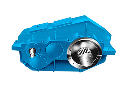
(1) According to the transmission type, the reducer can usually be divided into gear reducer, worm reducer and planetary reducer. Gear reducers are generally used for low-speed and high-torque transmission equipment. This type of reducer has high transmission efficiency, stable operation, long working life, small size, light weight, high carrying capacity, easy disassembly and inspection, easy installation, and simple maintenance. The gears used in the reducer are processed by technology and have the characteristics of high precision, good contact and high hardness of the tooth surface.
The overall worm reducer is compact, durable, strong load capacity, low noise, and can realize smooth motion transmission; when its outer size is small, a larger transmission ratio can be obtained, but the transmission efficiency is low. Planetary reducer is a type of reducer that mainly adopts planetary gear train transmission. It has the characteristics of large transmission ratio, compact structure, and relatively small size. Its structure is more complex than the previous two types of reducers, and its manufacturing accuracy requirements are higher. It is generally used for Requires compact structure and small power transmission system. The structure diagram of the internal reducer of the three reducers is shown in the figure.
(2) According to the number of transmission stages, reducers can usually be divided into single-stage reducers and multi-stage reducers. Single-stage reducer is a single-stage transmission mechanism composed of gears or worm gears. It is the simplest transmission mechanism. Its structure is as simple as gear reducer structure diagram, worm reducer structure diagram, planetary reducer structure The diagram is shown on the left. The two-stage and above two-stage reducers are collectively referred to as multi-stage reducers. The structure diagram of the gear reducer, the structure diagram of the worm reducer, and the structure diagram of the planetary reducer are shown in the figure on the right, which shows the structure of the two-stage reducer. Figure. When designing a two-stage and above two-stage reducer, considering that the transmission ratio of each stage has a greater impact on the overall size, weight and lubrication method of the reducer, the transmission ratio of each level is reasonably allocated. very important. Generally, the following basic principles are mainly followed when assigning various transmission ratios:
1. Make the load capacity of each transmission approximately equal;
2, Make the oil immersion depth of the large gears in each transmission roughly the same, so as to facilitate lubrication;
3, Make the overall size and weight of the reducer as small as possible.
(1) According to the layout of the transmission, the reducer can usually be divided into an expand reducer, a split reducer and a coaxial reducer. Two-stage and above two-stage reducers mainly have three transmission arrangements, namely, expansion, split and coaxial transmission. The transmission arrangement of two-stage cylindrical gear reducers is shown in the figure.
It can be seen from the figure that among the three layout forms, the expansion is the simplest. However, it can be seen that the bearing arrangement on both sides of the unfolded gear is not symmetrical, so the load distribution along the tooth width is uneven. In the split flow type, the bearings on both sides of the gear are arranged symmetrically, and the low-speed stage with a larger load is located in the middle of the two bearings, so the uneven distribution of the load along the tooth width is better. The high-speed gears of this type of reducer usually use helical gears, one side is left-handed and the other side is right-handed, which can offset the axial force. The coaxial input and output shafts are on the same straight line, so the box is relatively short. However, this type of reducer has a large axial size, a long intermediate shaft, and is generally heavy, which easily leads to uneven load distribution along the tooth width.


