Views: 3 Author: Site Editor Publish Time: 2020-08-24 Origin: Site

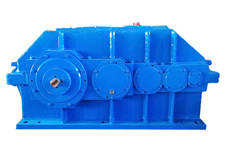
The reducer is a whole composed of various components. In addition to paying enough attention to the structural design of gears, shafts, bearing combinations and box bodies, the lubrication, oil injection holes, oil drain holes, observation mirrors, and ventilation of the reducer should also be considered. Reasonable selection and design of auxiliary parts and components such as lifting holes for mounting, installation and dismantling, anchor bolts of fixed equipment, shaft end caps, upper and lower boxes and seals.
Oil injection hole: The oil injection hole is mainly composed of the oil filling hole on the upper part of the reducer and the bearing grease injection hole. Because of the different design principles of each reducer, the upper end plate cover of some reducers can also add lubricating oil and check the internal gear box of the reducer. The function of the gear, bearing grease is added manually through the oil injection joint or lubrication pump.
Oil drain hole: When the gearbox reaches the oil change interval or the gearbox lubricating oil is unqualified, the oil needs to be drained. The plug or valve can be unscrewed to drain the oil. The oil drain hole is located at the bottom of the reducer, considering the reducer Whether the internal lubricating oil is discharged completely, an inclined plate is often installed at the bottom of the reducer to ensure that the lubricating oil is completely discharged.
Observation mirror: Large reducers are equipped with an observation mirror and oil mark. You can directly view the position of lubricant addition and operating conditions in the reducer without disassembly or assembly through the observation mirror. Small reducers are usually equipped with oil marks or oil glasses. , The oil mark and oil mirror are generally fixed on the reducer case body by screws, and the appropriate oil level of the reducer is clearly marked to facilitate customer management.
Ventilation cap: When the reducer is running, the temperature rises and the internal pressure increases. The ventilation cap acts to balance the internal and external pressures of the reducer. When the reducer is stopped, the temperature of the reducer decreases, and the external pressure is greater than the internal pressure, and air can pass through the ventilation. When the outside air enters the accelerator, some dust and moisture in the air will directly cause rust inside the reducer and cause lubricating oil pollution, which will increase the failure of the gearbox. For this reason, the venting tube not only avoids and installs filter elements in the structural design, to ensure the cleanliness of the lubricating oil.
Hoisting hole: When the reducer reaches a certain quality, in order to ensure convenient assembly and on-site installation, a hoisting device is designed on the reducer. Some hoisting devices are integrated with the reducer, and some are designed with lifting lug screw holes.
Anchor bolts: The speed reducer generally has a high speed. The reducer needs to be installed and positioned at the designed position to prevent the reducer from being displaced due to load and vibration, which will affect the installation work of the reducer and the motor and cause mechanical failure. An anchor bolt hole is designed at the bottom of the reducer, and it is integrated with the foundation through grouting. If disassembly is required during maintenance, only the anchor bolt nut needs to be unscrewed.
Shaft end cover: Fix the position of the shaft system components. Generally, there are seals and shaft sleeves in the bearing end cover. The bearing end cover is fixed on the reducer by bolt connection to seal and bear a certain load. The reducer is generally damaged All should be caused by bearing failure. When the bearing is damaged, the bearing end cover can be disassembled to replace it for easy maintenance.
Sealing parts: Sealing is also a very important part of the reducer. The main function is to prevent the infiltration or leakage of the medium in the independent space.
Unpacking screws: In order to ensure the sealing effect of each end cover of the gearbox and the upper and lower boxes, usually not only seals are used on the sub-box surface during assembly, but also water glass or sealant is applied to it, so it is often tightly cemented during disassembly. It is difficult to open the lid. For this reason, 1-2 screw holes are symmetrically machined at a suitable position of the box cover (easy to use tools). When disassembling, unscrew the bolts on the sub-box surface, screw the bolts into the screw holes of the box lifting bolts, and perform symmetrical support. Disassembly.


